RAK18001 WisBlock Buzzer Module Quick Start Guide
Prerequisite
What Do You Need?
Before going through each and every step on using RAK18001 WisBlock module, make sure to prepare the necessary items listed below:
Hardware
- RAK18001 WisBlock Buzzer module
- Your choice of WisBlock Base
- Your choice of WisBlock Core
- USB Cable
- Li-Ion/LiPo Battery (optional)
- Solar Charger (optional)
Software
- Download and install Arduino IDE.
- To add the RAKwireless Core boards on your Arduino Boards Manager, install the RAKwireless Arduino BSP.
Product Configuration
Hardware Setup
WisBlock can integrate this module, which makes it easy to build up an audible high-pitched sound. That sound can be used in various alarm and notifier applications. The RAK18001 is a WisBlock module that uses a MLT-5020 as its built-in buzzer.
For more information about RAK18001, refer to the Datasheet.
RAK18001 module can be connected to Slot A, B, C, or D of WisBlock Base to communicate with the WisBlock Core. It will work in any of the mentioned slots. However, you need to consider the specific pin assigned in that slot to control the RAK18002. The table below shows the default IO pins used:
| SLOT A | SLOT B | SLOT C | SLOT D |
|---|---|---|---|
| IO1 | IO2 | IO3 | IO5 |
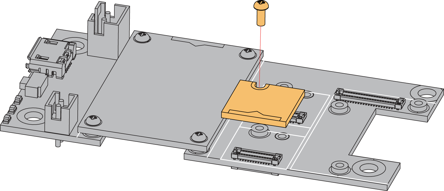
Also, always secure the connection of the WisBlock module by using the compatible screws, as shown in Figure 1.
Assembling and Disassembling of WisBlock Modules
Assembling
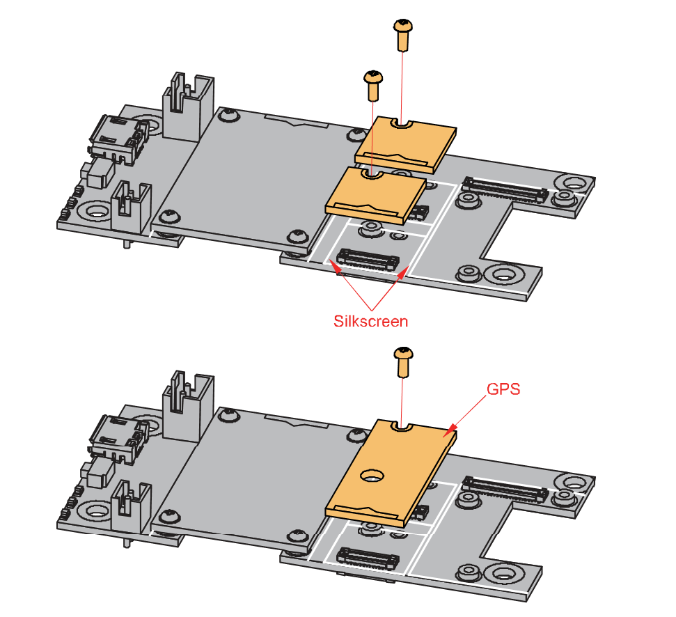
As shown in Figure 2, the location for Slot A, B, C, and D are properly marked by silkscreen. Follow carefully the procedure defined in RAK5005-O module assembly/disassembly instructions to attach a WisBlock module. Once attached, carefully fix the module with one or more pieces of M1.2 x 3 mm screws depending on the module.
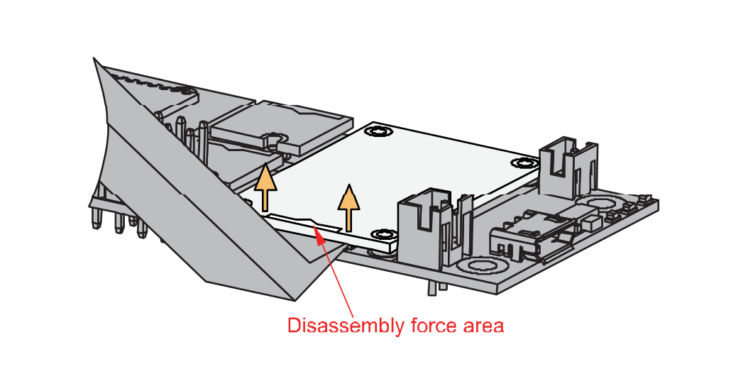
Disassembling
The procedure in disassembling any type of WisBlock modules is the same.
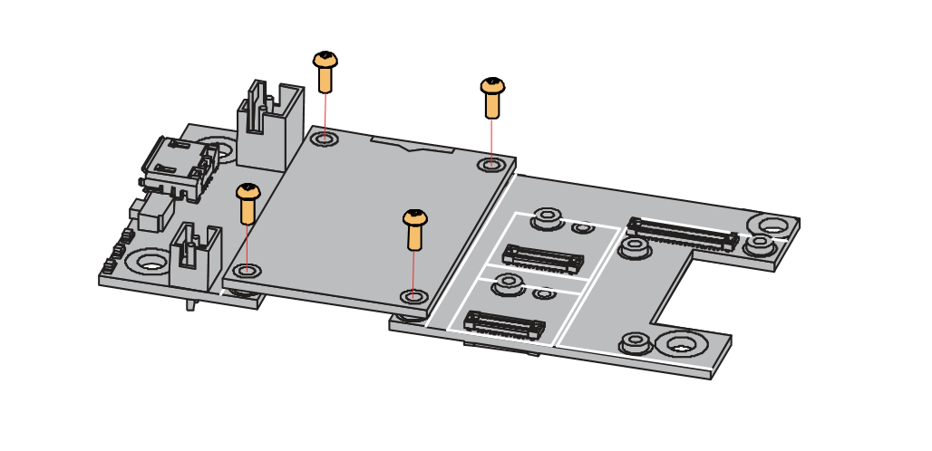
- To begin disassembling, remove the screws.
- After removing the screws, check the silkscreen of the module to find the correct location where force can be applied.
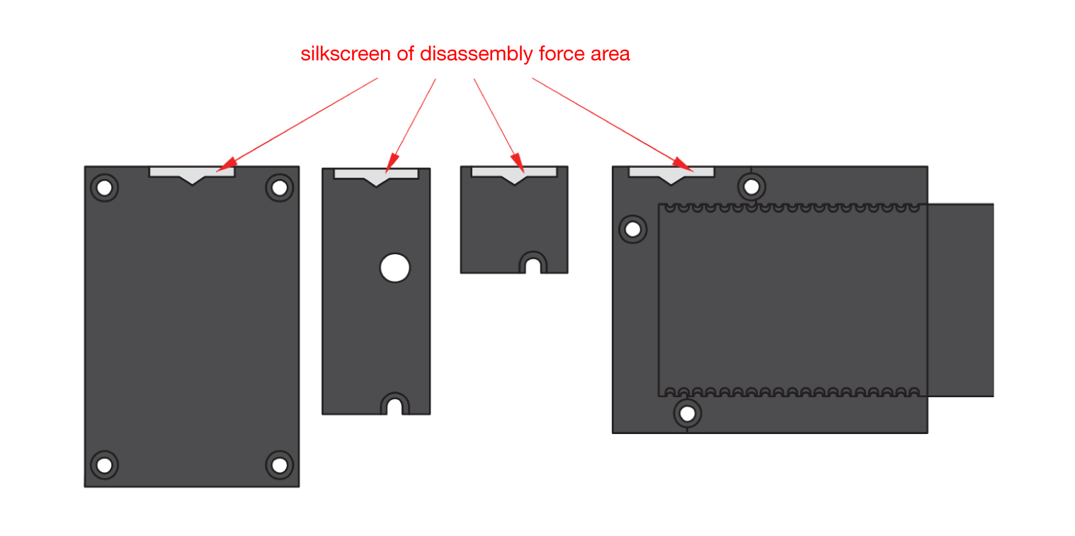
- Detach the module from the baseboard by applying force to the module at the position of the connector, as shown in Figure 5.
If you will connect other modules to the remaining WisBlock Base slots, check on the WisBlock Pin Mapper. This tool finds possible pin conflicts.
After all this setup, you can now connect the battery (optional) and USB cable to start programming your WisBlock Core.
Software Configuration and Example
The RAK18001 WisBlock Buzzer Module is designed to be part of a production-ready IoT solution in a modular way. It must also be combined with a WisBlock Core and a Base module. The sound and loudness can be controlled through PWM (Pulse-Width Modulation) signal from a WisBlock Core.
For RAK18001, the default accessible IO pin assignments are defined as follows which are used on different connection slots:
WB_IO1for IO1 on SLOT AWB_IO2for IO2 on SLOT BWB_IO3for IO3 on SLOT CWB_IO5for IO5 on SLOT D
Make sure to set the PWM pin to LOW with digitalWrite(BUZZER_CONTROL, LOW); after playing a sound. This is to ensure that the buzzer on the RAK18001 is in complete shut down and does not get hot.
However, you can change the IO pin assignments by switching the placement of the built-in resistor on the RAK18001. For more detailed explanation, refer to the Datasheet.
RAK18001 in RAK4631 WisBlock Core Guide��
If you have already installed the RAKwireless Arduino BSP, the WisBlock Core and example code should be available on the Arduino IDE.
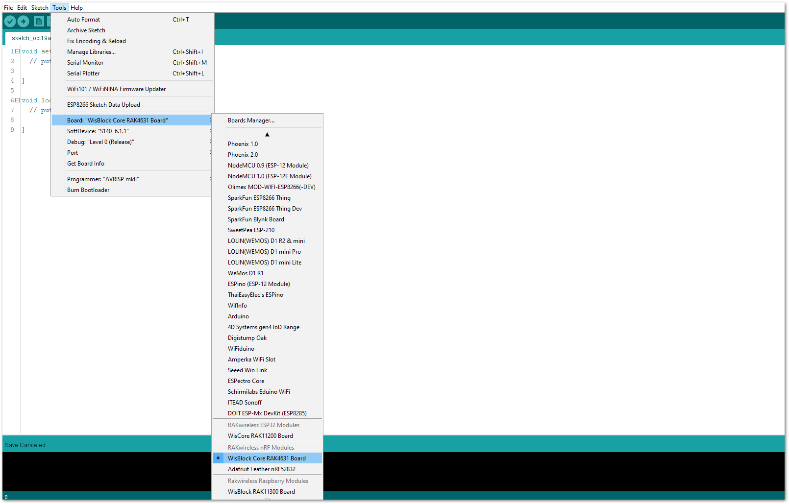
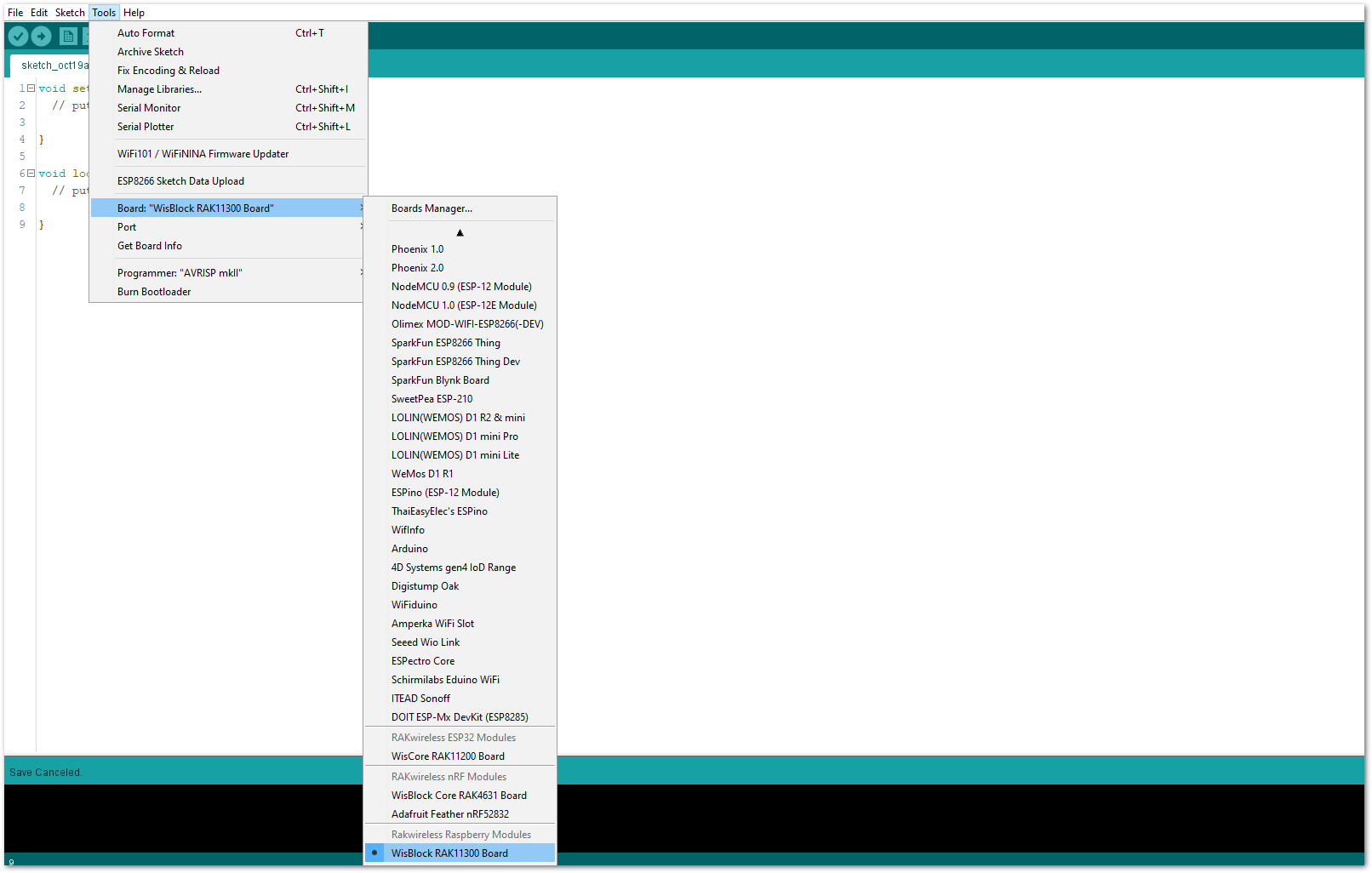
- To begin with the Arduino setup, you need to select the RAK4631 WisBlock Core.
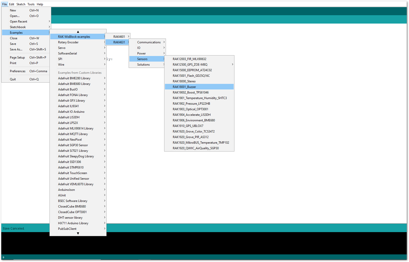
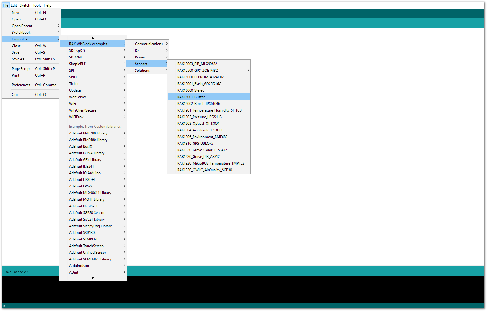
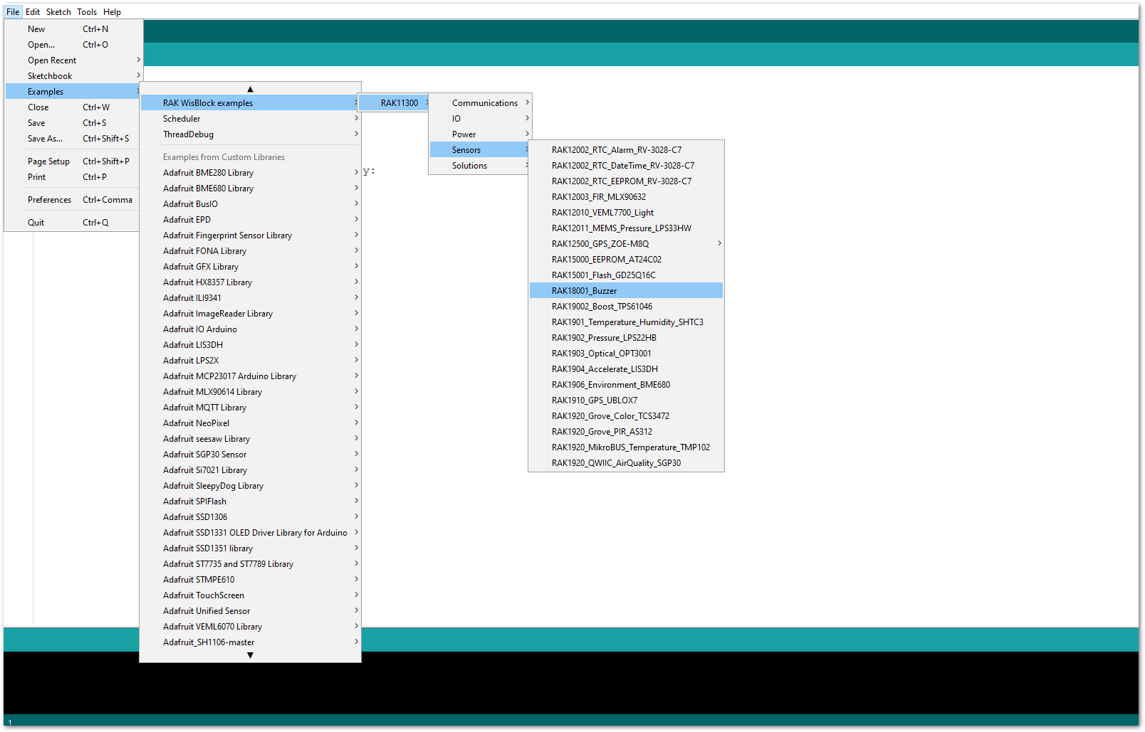
- The Basic Sample Code for RAK18001 in GitHub will work on RAK4631 WisBlock Core. You can also open the example codes depending on your WisBlock Core, as shown in Figure 7.
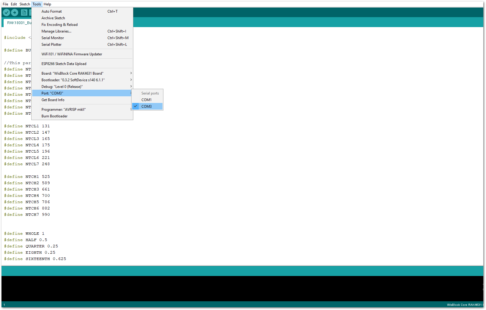
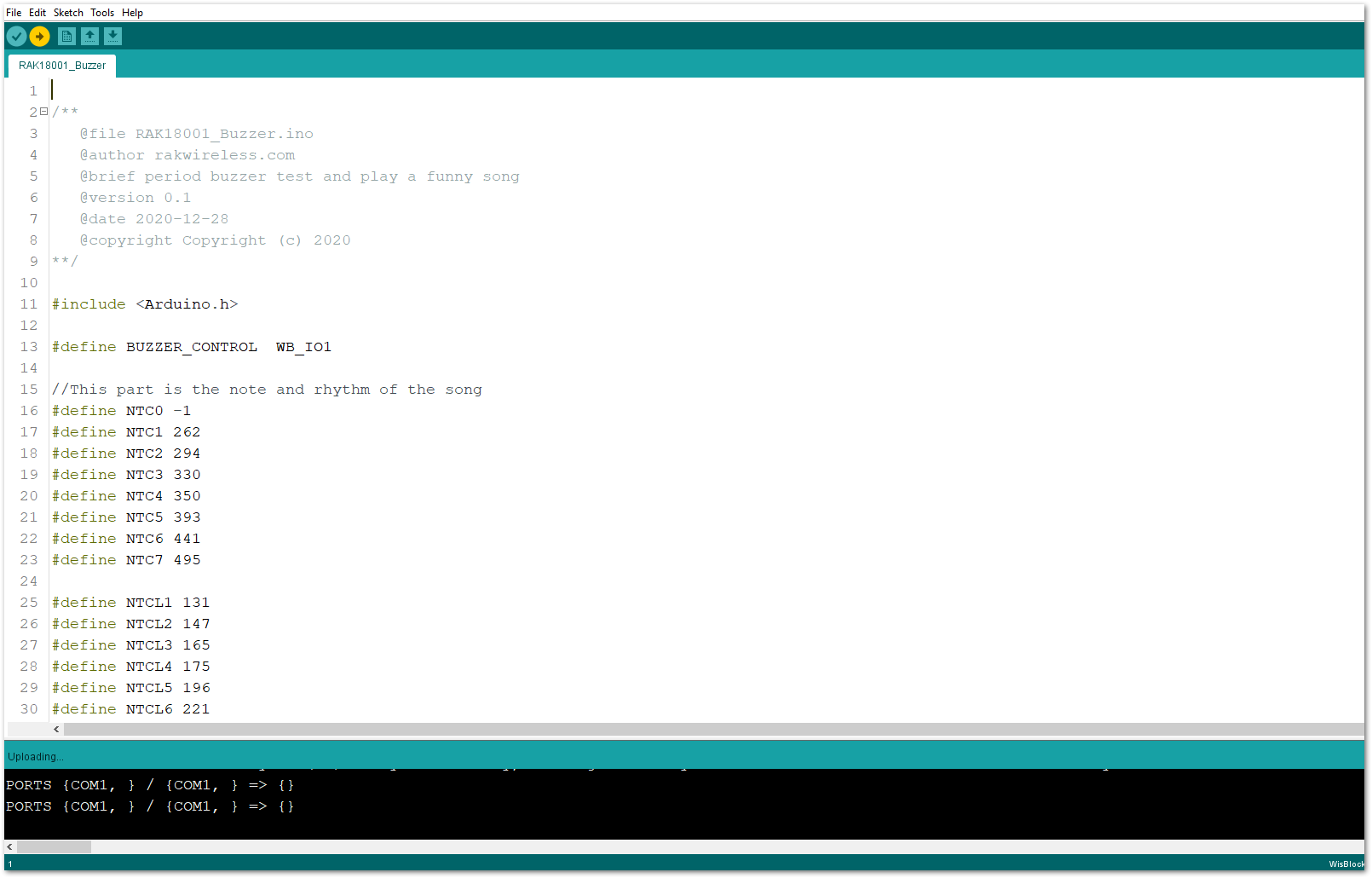
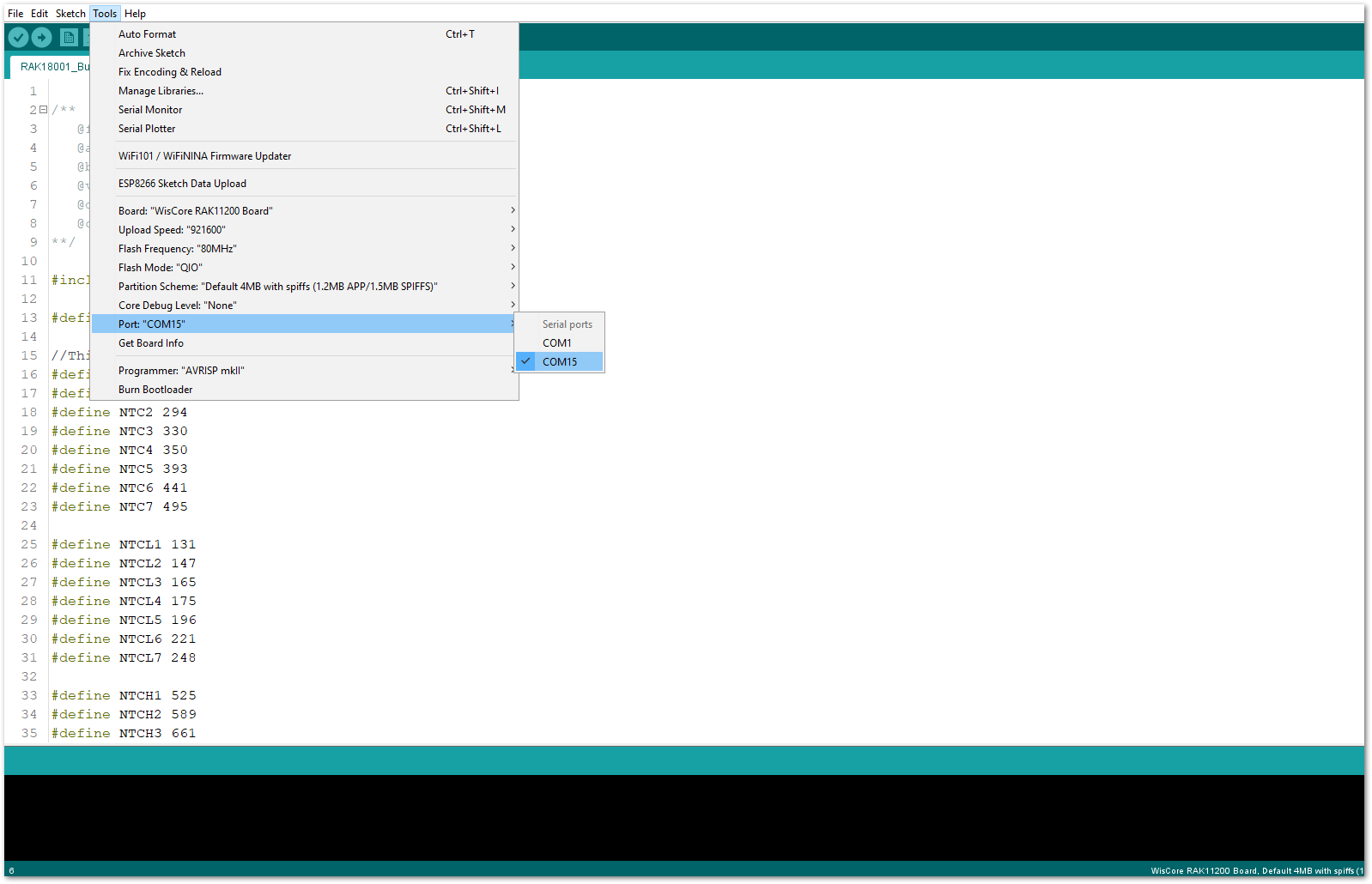
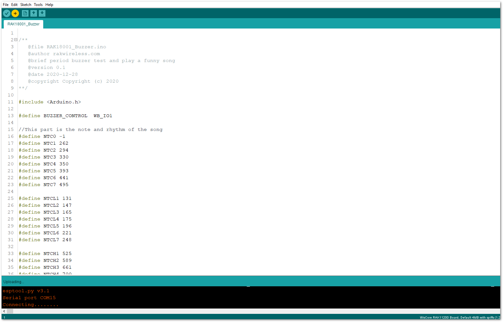
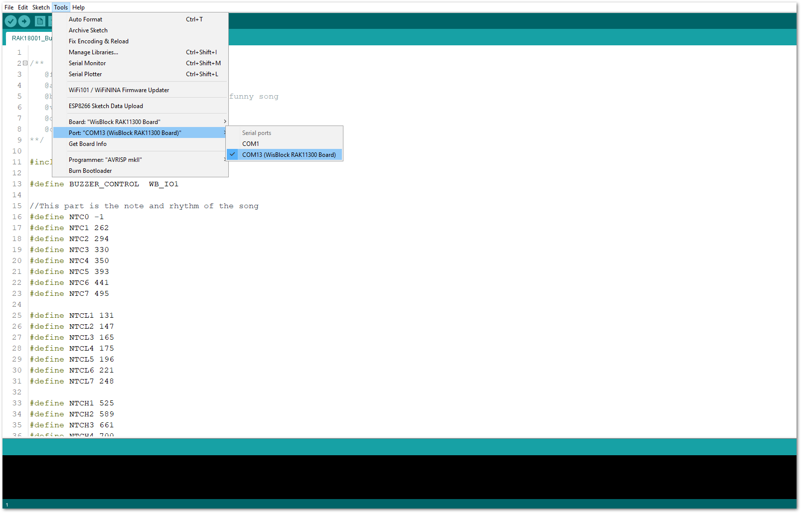
- After that, select the right serial port and upload the code, as shown in Figure 8 and Figure 9.
- When you have successfully uploaded the example sketch, you'll now be able to hear the RAK18001 WisBlock Buzzer module's sound. The output sounds and pitch level can be customized on the example code. It is even possible to play some various melody on it.
Make sure to set the PWM pin to LOW with digitalWrite(BUZZER_CONTROL, LOW); after playing a sound. This is to ensure that the buzzer on the RAK18001 is in complete shut down and does not get hot.
RAK18001 in RAK11200 WisBlock Core Guide
If you have already installed the RAKwireless Arduino BSP, the WisBlock Core and example code should be available on the Arduino IDE.
- To begin with the Arduino setup, you need to select the RAK11200 WisBlock Core.
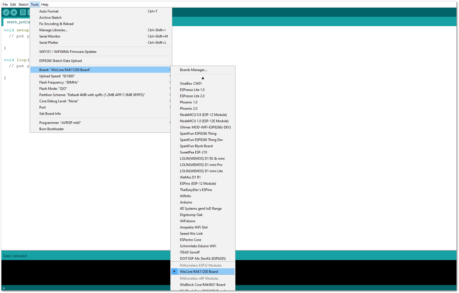
- The Basic Sample Code for RAK18001 in GitHub will work on RAK11200 WisBlock Core. You can also open the example codes depending on your WisBlock Core, as shown in Figure 11.
- After that, you can now select the right serial port and upload the code, as shown in Figure 12 and Figure 13.
RAK11200 requires Boot0 pin to be configured properly first before uploading. If not done properly, uploading the source code to RAK11200 will fail. Check the full details on the RAK11200 Quick Start Guide.
- When you have successfully uploaded the example sketch, you'll now be able to hear the RAK18001 WisBlock Buzzer module's sound. The output sounds and pitch level can be customized on the example code. It is even possible to play some various melody on it.
Make sure to set the PWM pin to LOW with digitalWrite(BUZZER_CONTROL, LOW); after playing a sound. This is to ensure that the buzzer on the RAK18001 is in complete shut down and does not get hot.
RAK18001 in RAK11310 WisBlock Core Guide
If you have already installed the RAKwireless Arduino BSP, the WisBlock Core and example code should be available on the Arduino IDE.
- To begin with the Arduino setup, you need to select the RAK11310 WisBlock Core.
- The Basic Sample Code for RAK18001 in GitHub will work on RAK11310 WisBlock Core. You can also open the example codes depending on your WisBlock Core, as shown in Figure 15.
- After that, select the right serial port and upload the code, as shown in Figure 16 and Figure 17.
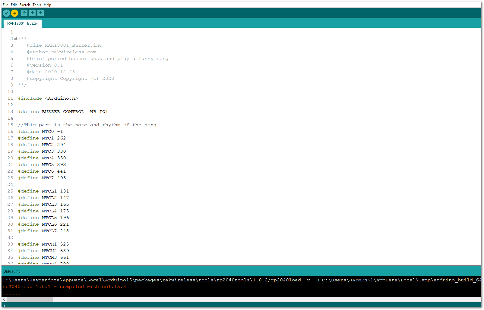
- When you successfully uploaded the example sketch, you'll now be able to hear the RAK18001 WisBlock Buzzer module's sound. The output sounds and pitch level can be customized on the example code. It is even possible to play some various melody on it.
Make sure to set the PWM pin to LOW with digitalWrite(BUZZER_CONTROL, LOW); after playing a sound. This is to ensure that the buzzer on the RAK18001 is in complete shut down and does not get hot.